CNC machines Axis
The real parts of a CNC program involves the input of co-ordinates of the tool endpoint to produce any machining profile, subsequently it is necessary to follow a proper co-ordinate system.
Cartesian Co-ordinate System:
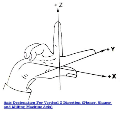
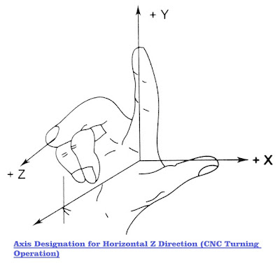
All the machine tools make use of the Cartesian coordinate system for the purpose of simplicity. The guiding coordinate system followed for assigning the axes is the familiar right hand coordinate system. The fundamental axes to be assigned are the rectangular axes and the rotary axes. One could use his right hand to arrive at these alternate variable positions of the same right hand coordinate system.
Designating the axes:
Z-Axis and Motion:
Location:
The Z-Axis movement is either along the shaft pivot axle or parallel to the shaft pivot axle. In the case of machine without a shaft / spindle such as shapers and planers, it is identified as the one perpendicular to the table, which passing through the controlled point (e.g., the cutting tool tip).
Direction:
The tool moving far from the work-holding surface towards the cutting tool is assigned as the positive Z direction. This means in a drilling machine the drill moving into the work-piece is the negative (-) Z direction. This aids in decreasing the possible accidents because of the wrong part program entry in the coordinate signs.
When there are several shafts and slide ways:
In such cases, one of the shafts, preferably the one perpendicular to the work holding surface may be chosen as the standard shaft. The primary Z movement is then close to the primary shaft. The tool movements of other spindle quills or sometimes slides, these movements are termed as secondary and tertiary movements, and they are designated as U, V, W and P, Q, R respectively. For other machines such as shaper, planer etc. , the positive (+) Z movement increases the clearance between the work surface and the tool holder.
X – Axis:
The X – Axis is the principle motion direction in the positioning plane of the cutting tool or the work-piece.
Location:
It is perpendicular to the Z – Axis and should be horizontal and parallel to the work holding surface wherever possible.
Direction:
When looking from the principle spindle to the column, the positive (+) X is to the right. For turning machines, it is radial and parallel to the cross slide. X motion is positive when the tool withdraws from the axis of rotation of the work-piece. For other machine tools, the X – Axis is parallel to and positive along the principle direction of movement of the cutting or the guided point.
Y – Axis:
It is perpendicular to both X – and Z – axis and the direction is identified by the right hand Cartesian coordinate system.
Rotary Motions:
A, B and C movements define the primary rotary motions.
Location:
These movements are located about the axis parallel to X, Y and Z respectively. If it in count to the above mentioned primary rotary motions, there are secondary rotary motions. These should be designated as D or E regardless of whether they are parallel or not to A, B and C motions.
Direction:
Positive A, B and C are in the directions which advance right hand screws in the positive X, Y and Z directions respectively. The fingers of the right hand point towards the positive direction of the rotary motions. All the above mentioned (e.g., X, Y, Z; U, V, W; P, Q, R; A, B, C and D, E) is the reference to a point, the movement of which is sought to be controlled. This point is generally the tip of the cutting tool. Often the tool point may not move in some directions, e.g., the quill of the spindle of a vertical milling machine moves in the Z direction but not in the X and Y directions. In such problems, the work surface is usually motioned in a direction opposite to the one projected for the tool, e.g., the table of the milling machine holding the work piece may be moved in – X and – Y directions. Such movements of machine elements, – X or –Y are signified as + X or + Y respectively. Prepared letters can thus be used for all the afore-mentioned motions to show the corresponding reversed directions for moving work surfaces.


Comments
Post a Comment